I am starting a fresh reply.. Thanks to Apple mods.
I have done a pinout here for the 8 pin version.
https://sites.google.com/site/lapastenague/a-deconstruction-of-routers-and-modems/apple-time-capsule-repair/repair-ac-version-time-capsule-or-extreme
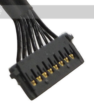
Numbered from left.. 1-3 +12v, 4,5,8 Gnd and 6,7 which are clearly finer wires are temp sensor which you can trace back on the board to a surface mount transistor in typical temp diode mode.
The 10 pin plug
I have never seen one in the flesh so to speak.. on my repair bench to be more exact.
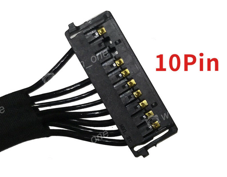
The wiring is clearly re-arranged.. but my guess is as follows.. please do test carefully with a multimeter.
WARNING .. DANGER.. TEST BEFORE USE.
Counting pin1 as bottom of the screenshot..
1-3 still +12v
4, 7, 10 Gnd
5, 6 temp sensor. Still the finer wires. Clearly not used to carry current.
You will have to use diode range on your multimeter to work out if they are wired with the same orientation as the original power supply.. I would expect it to.
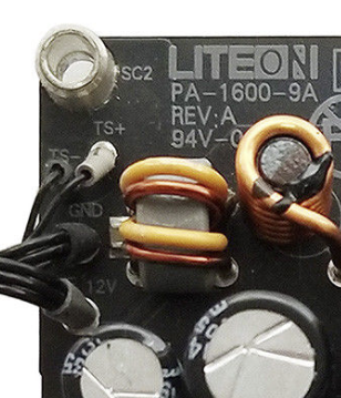
They are actually marked on the board shown below as TS+ and TS- ..
It is incredibly easy to test the power pins.. look on the power supply board.. measure if 1-3 are all connected to the same point.. measure if 4, 7, 10 are all connected to the same point. If not measure and redo the pinout.
The positive and negative posts on the board will not change. And are clearly marked.