Looks like no one’s replied in a while. To start the conversation again, simply ask a new question.

Building a rectangle template for FCPX that can be manipulated via x,y,w,h handles rather than center w h

Hi,


I make a lot of screencast videos at the moment and a recurrent task is to highlight a rectangular area of the screen and get this pixel perfect.


There's not much in FCPX to do this with out of the box (apart from the awkward "shape" thingy), so I bought a plugin (mTutorial) that has a lot of different ways of marking out rectangular areas and much besides.


Unfortunately all of those transitions have centre + width + height handles, which makes it super awkward to correctly place the rectangle. First get pretty much into the centre, then adjust the width, then adjust the height, recenter the whole thing, pull a bit on the width, etc..


So I took it upon myself to build a simple Motion template to just get a transparent rounded rectangle onto the screen, but I have found this to be unexpectedly difficult to do. While rectangles can be adjusted using normal top left origin + height + width handles in Motion, publishing the rectangle so that it has any handles at all is defeating me at the moment.


I'm a Motion noob, but a Mac programmer of 25+ years experience, but I can't seem to get a handle on this problem.. it looks.. impossible.. but that can't be right?


  1. how do I get any positioning handles to appear in FCPX?
  2. is there any way of changing the anchor point of a shape so that it sticks to the top left independently of the width/height?


Other tools I've used have the ability to make calculations (e.g. anchorPointX = centerX - (width/2)) and I've been trying to find something similar in the behaviours but to no avail.


Any pointers would be much appreciated.

Posted on Jun 14, 2022 2:35 AM

Reply
Question marked as Best reply

Posted on Jun 14, 2022 7:30 PM

It's been a few years since I wrote those... I've adopted a few changes since then.


First, adding OSC filters to a Color Solid (or other shape object) is more convenient and that's what I'll use here.


This is a recipe tutorial, so try to hang in there! Project Size 1920x1080.


You need:

1 Rectangle

1 Color Solid

: 2 OSC filters (Poke is the "typical" one to use)

8 Numbers Objects


Start with adding a Color Solid. To the Color Solid, add 2 Poke filters. Set their Mix values to 0%. Name one topLeft and the other botRight (or just abbreviate tl and br).


Add Object > Generators > Text Generators > Numbers.

Uncheck Animate.

Duplicate this object 7 times (8 total).

Name them:

projectWidth, projectHeight, convH-br, convH-tl, diffH, convV-br, convV-tl, diffV. We need the project dimensions, we need to **convert** between OSC dimensions (which are always 0 - 1 in both directions regardless of pixel count), we need the differences between the H(orizontal) values and the V(ertical) values in pixels.


for:

projectWidth, set the Numbers Value to 1920.

projectHeight = 1080.


convH-br, to the Value parameter, Add Parameter Behavior > Link. To Source Object drag and drop projectWidth and Source Parameter > Object.Numbers.Value (should be automatic). Add **another** link to the Value. Set Apply Mode to Multiply by Source. Add Color Solid to Source Object; Source Parameter > Filters.br.Center.X. Set the Scale to 0.01.


convH-tl:

Add Parameter Behavior > Link to Value as above. Repeat steps until Color Solid > Filters.tl.Center.X


diffH

Add Parameter Behavior > Link to Value. Add convH-br to Source Object; Set the Value Offset to -4.0(* - I'll explain later).

Add another Link to Value. Set Source Object to convH-to to Source Object; set Apply Mode to Add to Source; Set Scale to -1.0 (to subtract).


For convV-br, convV-tl and diffV, repeat the same steps, except for the Y values. For diffV Value Offset, set it to -2.0.


Create a Rectangle, preferably in a New Group (so you can turn off all the "noise" in the other group).

Add Link To Properties > Transform > Anchor Point.X. Drag the Rectangle to the Source Object. For the Source Parameter, select Object Attributes > Size > Width. Set the Scale to -0.5.


Add Link to Properties > Transform > Anchor Point.Y. Drag the Rectangle to the Source Object and set the parameter to Object Attributes > Size > Height. Set the Scale to 0.5 (positive 0.5 -- values go from the bottom to the top in the V dimension).


These two actions will continuously set the Anchor point to the top left position of the Rectangle. Continuing...


Add a Link to Properties > Transform > Position.X To the Source Object, drag'n'drop the Color Solid and set Source Parameter to Filters > tl > Center.X. Set the X offset (at the very bottom) to -0.5.


Add a Link to Properties > Transform > Position.Y. To the Source Object, drag'n'drop the Color Solid and set Source Parameter to Filters > tl > Center.Y. Set the X offset to -0.5.


Go to the Rectangle > Shape > Geometry tab and Add a Link to Size > Width (dial down the disclosure triangle). To the Source Object, drag'n'drop the diffH Numbers object and set the Source Parameter to Object > Numbers > Value. Set the Scale to 0.1 (**)


Go to Rectangle > Shape > Geometry and Add Link to Size > Height. To the Source Object drag'n'drop diffV and set the Source Parameter to Object > Numbers > Value. Set the Scale to 0.1.


You should get rectangle control like:
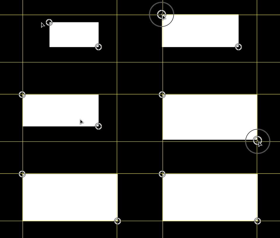


(* Rectangles are rendered with the left edge on the pixel boundary and right edge with an overlap. There appears to be about a 2pixel "edge" — even without an outline and so I subtract 4 total pixels to make the bottom right OSC line up "perfectly" with that corner.)

(** Motion maintains different counting values for different types of object parameters. You'll need to realize that you can run into these discrepancies and how to deal with them when you come across them. )


PS — this is NOT the only way to handle this situation. The extra Numbers objects are used to make this a more clear tutorial and easier to understand the "math" involved. That is: this is not exactly the same technique I used in other products I've made that do basically the same thing.


Similar questions

3 replies
Question marked as Best reply

Jun 14, 2022 7:30 PM in response to Frank Reiff

It's been a few years since I wrote those... I've adopted a few changes since then.


First, adding OSC filters to a Color Solid (or other shape object) is more convenient and that's what I'll use here.


This is a recipe tutorial, so try to hang in there! Project Size 1920x1080.


You need:

1 Rectangle

1 Color Solid

: 2 OSC filters (Poke is the "typical" one to use)

8 Numbers Objects


Start with adding a Color Solid. To the Color Solid, add 2 Poke filters. Set their Mix values to 0%. Name one topLeft and the other botRight (or just abbreviate tl and br).


Add Object > Generators > Text Generators > Numbers.

Uncheck Animate.

Duplicate this object 7 times (8 total).

Name them:

projectWidth, projectHeight, convH-br, convH-tl, diffH, convV-br, convV-tl, diffV. We need the project dimensions, we need to **convert** between OSC dimensions (which are always 0 - 1 in both directions regardless of pixel count), we need the differences between the H(orizontal) values and the V(ertical) values in pixels.


for:

projectWidth, set the Numbers Value to 1920.

projectHeight = 1080.


convH-br, to the Value parameter, Add Parameter Behavior > Link. To Source Object drag and drop projectWidth and Source Parameter > Object.Numbers.Value (should be automatic). Add **another** link to the Value. Set Apply Mode to Multiply by Source. Add Color Solid to Source Object; Source Parameter > Filters.br.Center.X. Set the Scale to 0.01.


convH-tl:

Add Parameter Behavior > Link to Value as above. Repeat steps until Color Solid > Filters.tl.Center.X


diffH

Add Parameter Behavior > Link to Value. Add convH-br to Source Object; Set the Value Offset to -4.0(* - I'll explain later).

Add another Link to Value. Set Source Object to convH-to to Source Object; set Apply Mode to Add to Source; Set Scale to -1.0 (to subtract).


For convV-br, convV-tl and diffV, repeat the same steps, except for the Y values. For diffV Value Offset, set it to -2.0.


Create a Rectangle, preferably in a New Group (so you can turn off all the "noise" in the other group).

Add Link To Properties > Transform > Anchor Point.X. Drag the Rectangle to the Source Object. For the Source Parameter, select Object Attributes > Size > Width. Set the Scale to -0.5.


Add Link to Properties > Transform > Anchor Point.Y. Drag the Rectangle to the Source Object and set the parameter to Object Attributes > Size > Height. Set the Scale to 0.5 (positive 0.5 -- values go from the bottom to the top in the V dimension).


These two actions will continuously set the Anchor point to the top left position of the Rectangle. Continuing...


Add a Link to Properties > Transform > Position.X To the Source Object, drag'n'drop the Color Solid and set Source Parameter to Filters > tl > Center.X. Set the X offset (at the very bottom) to -0.5.


Add a Link to Properties > Transform > Position.Y. To the Source Object, drag'n'drop the Color Solid and set Source Parameter to Filters > tl > Center.Y. Set the X offset to -0.5.


Go to the Rectangle > Shape > Geometry tab and Add a Link to Size > Width (dial down the disclosure triangle). To the Source Object, drag'n'drop the diffH Numbers object and set the Source Parameter to Object > Numbers > Value. Set the Scale to 0.1 (**)


Go to Rectangle > Shape > Geometry and Add Link to Size > Height. To the Source Object drag'n'drop diffV and set the Source Parameter to Object > Numbers > Value. Set the Scale to 0.1.


You should get rectangle control like:


(* Rectangles are rendered with the left edge on the pixel boundary and right edge with an overlap. There appears to be about a 2pixel "edge" — even without an outline and so I subtract 4 total pixels to make the bottom right OSC line up "perfectly" with that corner.)

(** Motion maintains different counting values for different types of object parameters. You'll need to realize that you can run into these discrepancies and how to deal with them when you come across them. )


PS — this is NOT the only way to handle this situation. The extra Numbers objects are used to make this a more clear tutorial and easier to understand the "math" involved. That is: this is not exactly the same technique I used in other products I've made that do basically the same thing.


Jun 14, 2022 5:49 PM in response to Frank Reiff

Hi


The general topic here is 'how to create on screen controls'.


There are 3 articles on this topic from Fox Mahoney that are essential reading, and likely to have the information you need.


https://fcp.co/final-cut-pro/tutorials/1835-the-mysteries-of-osc-in-final-cut-pro-x-revealed-part-1


https://fcp.co/final-cut-pro/tutorials/1837-controlling-shapes-the-mysteries-of-osc-in-final-cut-pro-x-revealed-part-2


https://fcp.co/final-cut-pro/tutorials/1842-the-final-cut-pro-x-osc-library-of-controls-mysteries-of-oscs-part-3


However, Motion is bound to a finite set of functions that can be published through to FCP. The only way to extend that range of function is to build your own tools externally with Fxplug. Motion VFX do various products directly in Motion, and others are built externally - it may not be the case that you can reproduce everything you see done by MotionVFX just with Motion alone.


For the anchor point - the tool you need to is the link behavior.


There are various ways to pin an anchor point to the corner - either by x anchor to left edge/y anchor to top edge, or by left anchor to widget ( scale of - .5) and y anchor to height (scale of -.5) ...i might have those incorrect - but the link behavior is the tool.


Building a rectangle template for FCPX that can be manipulated via x,y,w,h handles rather than center w h

Welcome to Apple Support Community
A forum where Apple customers help each other with their products. Get started with your Apple ID.